



Processo di piegatura della lamiera: A Practical Guide to Process Analysis
By Author: Mark Hanks
Introduzione
The sheet metal bending process is widely used in electromechanical, automobilistico, and aerospace industries for sheet metal forming enclosures, Armadi, and panels. Freni a pressa CNC cold-form sheets into various shapes using standard or custom tooling. The rationality of the sheet metal bending process directly influences final dimensions and part quality. This article shares practical techniques derived from analysis and experiments to support better sheet metal forming outcomes(An effective sheet metal bending process not only improves bending accuracy but also reduces material waste, and production costs. ).

1. Come calcolare la lunghezza della lamiera spiegata
During the sheet metal bending process, accurate unfolded length calculation is essential to make sure bending accuracy. Unfolded length depends on material thickness, Angolo di flessione, e stampatura.
1.1 Neutral Layer Method (for Non-Right-Angle Bends)
Durante la piegatura, the outer layer stretches and the inner compresses, while the neutral layer (between them) experiences neither stress. Its length stays constant, making it the reference for blank length. Its position varies with deformation: for thickness δ ≤ 4 mm, it lies at about 0.5δ from the inner surface; for δ ≥ 5 mm, at about 0.34δ. The neutral layer length equals the required unfolded blank.
•For material thickness δ ≤ 4 mm, the neutral layer distance from the inner surface is approximately 0.5δ.
•For thickness δ ≥ 5 mm, it is approximately 0.34δ.
The length of the neutral layer corresponds to the blank length required for the part.
1.2 Compensation Coefficient Method (for Right-Angle Bends)
It is possible to derive the empirical bending compensation coefficient for right-angle bends experimentally, and the unfolded dimension is calculated as:
L = A B − 2d 2D
Dove:
•L = lunghezza non spiegata
•A, B = external dimensions of the bent part
•δ = spessore del materiale
•Δ = compensazione dei coefficienti
Esempio: If A = 35 mm, B = 60 mm, and δ = 4 mm, then the length of the unfolded part = 88 mm.
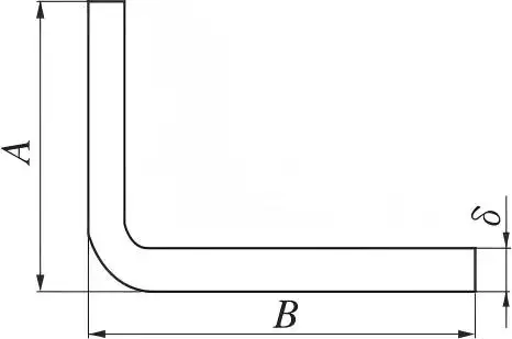
Fig.1 Figura di formazione a piegatura
Tabella 1: Bending Compensation Coefficients (Reference Values)
| Thickness δ (millimetro) | Coefficiente di compensazione Δ | Common V-Die Opening V (millimetro) |
| 1.0 | 0.1 | 6 |
| 1.5 (1.2) | 0.2 | 9 |
| 2.0 | 0.3 | 12 |
| 2.5 | 0.3 | 16 |
| 3.0 | 0.4 | 20 |
| 3.5 | 0.4 | 20 |
| 4.0 | 0.5 | 25 |
| 5.0 | 0.6 | 32 |
| 6.0 | 0.8 | 32 |
| 8.0 | 1.2 | 55 |
�� Note: When bending long workpieces where the pressure exceeds the press brake's tonnage limit, a non-standard V-die opening may be required. The compensation coefficient should be adjusted based on trial bending results. Ad esempio:
•5 mm thick sheet: standard V-die 32 mm (Δ = 0.6); if length approaches 3000 mm, use 55 mm V-die and reduce Δ by 0.1.
•For a 6 mm thick sheet ≥ 2000 mm long, select a 55 mm V-die and set Δ at 0.4 (adjusted from 0.8).
Compensation coefficients are values developed empirically for a specific press brake and associated tooling and the specific material. They should be determined afresh for each case.
2. Come scegliere gli utensili per freni a pressione
A critical aspect of the bending of sheet metal is the selection of appropriate tooling. Press bending tooling, as a system, consists of a punch (Die superiore) e un dado (Die inferiore). The selection is determined by the nature of the material, its thickness, and the dimensions of the bending to avoid a collision of the workpiece and the tooling and also to avoid damage to the die or the bending machine due to the inappropriate selection of the V-die opening.
2.1 Lower Die (V-Die) Selection
Standard lower press brake dies frequently have several V-shaped openings of varying widths and angles on a single die block. For standard operations, the V-die opening will be in the order of 6 to 8 times the thickness of the sheet. For thinner sheets, and where a bend of a larger radius is desirable, a wider opening will be chosen. The V-die opening may be of a standard shape and size, or may be modified, or fashioned, or made, to satisfy a specific requirement.
Tabella 2: Recommended B-Die Openings
| Spessore del materiale (millimetro) | Recommended B-Die Openings (millimetro) | Moltiplicatore di zonizzazione |
| 1.0 | 6 - 8 | 6× - 8× |
| 1.5 | 9 - 12 | 6× - 8× |
| 2.0 | 12 - 16 | 6× - 8× |
| 3.0 | 18 - 24 | 6× - 8× |
| 4.0 | 24 - 32 | 6× - 8× |
| 5.0 | 30 - 40 | 6× - 8× |
| 6.0 | 36 - 48 | 6× - 8× |
| 8.0 | 48 - 64 | 6× - 8× |
2.2 Upper Die (Punch) Selection
1) Colpi dritti
• Utilizzato per piegare fogli di spessore
2) D ≤ 3 mm
• Utile per curve con operazioni multiple
3) Colpi al collo d'oca
• Progettato per parti a forma di U di profondità variabile
• Piccoli punzoni a collo d'oca usati per parti poco profonde
• Punzoni a collo d'oca grandi usati per le parti profonde di materiale spesso
4) Schiacciamento dei pugni
• Utilizzato per appiattire i bordi piegati di parti rielaborate
•Modifiche personalizzate in grado di soddisfare requisiti di design unici
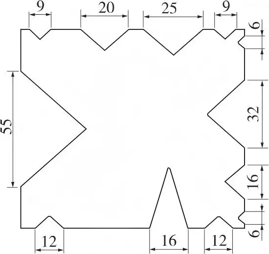
Fig.2 Figura della sezione trasversale inferiore del die
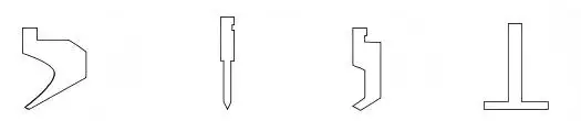
Lama grande curva Lama dritta Lama piccola curva Lama appiattita
Fig.3 Figura della sezione trasversale superiore del dado
3. Come calcolare la forza di flessione del freno a pressione
All bending tools have built-in safety features against high pressures, tuttavia, each tool has a unique safety limit that must not be exceeded. Prior to bending, it must be confirmed that the bending force would not exceed the press brake's tonnage limit, based on the thickness of the sheet and the required bending length.
One of the equations for calculating bending force is:
P = (1.6 × B × δ² × Rm) / (100 × V)
In questa equazione:
•P = bending force (tono)
•δ = thickness of the material (millimetro)
•B = width of the sheet (millimetro)
•V = V-die opening width (millimetro)
•Rm = material tensile strength (MPa)
The restriction on bending tonnage is determined by the specific press brake and the tooling used. Most bending machines have a tonnage rating plate attached to the frame, and tonnage can also be verified through CNC bending simulation systems.
Table 3: Carbon Steel Bending Tonnage Limits (Reference Values)
| Spessore (millimetro) | V-Die (millimetro) | Max Length (millimetro) | Max Tonnage (t) |
| 0.8 | 6 | 3000 | 25 |
| 1.0 | 6 | 3000 | 39 |
| 1.5 | 9 | 3000 | 54 |
| 2.0 | 12 | 3000 | 84 |
| 2.5 | 16 | 3000 | 84 |
| 3.0 | 20 | 3000 | 98 |
| 3.5 | 20 | 3000 | 133 |
| 4.0 | 25 | 3000 | 141.3 |
| 4.5 | 25 | 2500 | 150 |
| 5.0 | 32 | 2500 / 1700 | 150 / 145 |
| 6.0* | 55 | 3000 | 150 |
| 8.0* | 55 | 1600 | 145 |
| 10.0* | 55 | 1000 | 140 |
�� Notes:
•Maximum bending length for carbon steel is 3100 mm; theoretical tonnage should not exceed 150 tons.
•Items marked with * exceed the standard limit and would require program adjustments; this carries safety risks and is not generally recommended.
•When a part exceeds the tonnage limit, alternative approaches may include cutting process slots along the bend line or V-grooving the sheet to reduce material thickness.
Table 4: Stainless Steel Bending Tonnage Limits (Reference Values)
| Spessore (millimetro) | V-Die (millimetro) | Max Length (millimetro) | Max Tonnage (t) |
| 0.8 | 6 | 3000 | 25 |
| 1.0 | 6 | 3000 | 39 |
| 1.5 | 9 | 3000 | 54 |
| 2.0 | 12 | 3000 | 84 |
| 2.5 | 16 | 3000 | 84 |
| 3.0 | 20 | 3000 | 98 |
| 3.5 | 20 | 3000 | 133 |
| 4.0 | 25 | 3000 | 141.3 |
| 4.5 | 25 | 2500 | 150 |
| 5.0 | 32 | 2500 | 150 |
| 6.0* | 55 | 3000 | 150 |
| 8.0* | 55 | 1600 | 145 |
| 10.0* | 55 | 1000 | 140 |
�� Notes: Similar to carbon steel, stainless steel has a maximum bending length of 3100 mm with a theoretical tonnage limit of 150 tons. Items marked with * exceed the standard limit and require program adjustments, which carry safety risks. If components surpass the tonnage limit, it could be reasonable to modify the sheet metal bending process.
4. Tipi comuni di parti piegate in lamiera
4.1 Parti a forma di U
Different sheet metal bending process designs are required for U-shaped, Z-shaped, and other complex parts. For U-shaped parts, a general guideline is that the bend height H should be less than or equal to the bend width B to avoid tool interference. Tuttavia, even when H ≤ B, interference may still occur if the bend height is excessive—typically when H ≥ 80 mm, the part may contact the bending machine housing during bending.
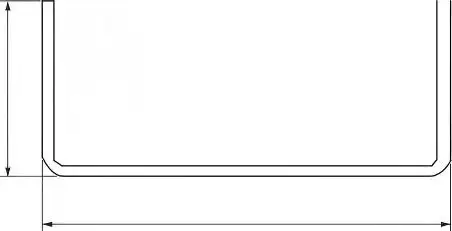
Fig.4 Figura di formazione della piegatura
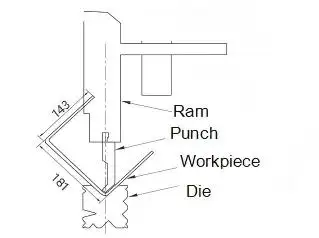
Fig.5 Diagramma di simulazione della flessione
Potential solutions may incorporate the following features:
•Bending an obtuse angle first (to allow the flanges to clear the bending machine), then the right-angle bend, and then the intermediate bend may also be flattened. (Note: This approach will likely leave visible marks on the workpiece.)
•Use of gooseneck punches (when H ≥ B) can be used, but the application of this approach may need to be verifiable through trial simulation or actual bending.
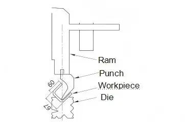
Fig.6 Diagramma di simulazione della flessione
4.2 Parti a forma di Z
The possibility of incorporating Z-shaped bends is primarily determined by the distance from the V-die opening to the edge of the part. An acceptable approach may be:
•Choosing the correct V-die opening and punch based on the thickness of the material.
•Drawing or simulating the shape that will be formed.
•If you're still not sure, conduct some physical simulations or bend the machine as a test.
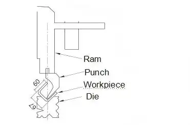
Fig.7 Diagramma di simulazione della curvatura
5. Problemi e soluzioni comuni di piegatura della lamiera
Several problems may occur in the bending of sheet metal. The table below summarises typical problems and practical solutions.
| Discendenza | Possibile mitigazione |
| Altezza insufficiente della flangia di flessione | • Increase flange dimension if design allows.• Use a smaller V-die opening (check tonnage) and adjust compensation.• For δ ≤ 3 mm: H ≈ V/2 + 2; for δ > 3 mm: H ≈ V/2 + 4. |
| Deformazione del foro sulla linea di curvatura | • Drill holes after bending.• Cut process slots along the bend line (slot length ≈ hole diameter).• Keep hole edge at least half V-die width from bend line. |
| Interferenza con utensili | • Adjust bending sequence—complex edges first, then simple edges.• Use specialized tooling (e.g., gooseneck punches or offset dies). |
| Crepa alla curva | • Orient bend line perpendicular to rolling direction.• Anneal the bend area or choose a material with better ductility. |
| Segni superficiali sulla parte piegata | • Increase punch radius through tool modification.• Use non-marking lower dies.• Put protective film between die and sheet. |
| Posizionamento di difficoltà per flange irregolari | • Mark bend lines during laser cutting as a reference.• Create a fixture matching the contour of the part. |
| Dimensioni formate non come specificato | • Use a common reference point to reduce cumulative error.• Perform practice bends and determine compensation coefficient. |
6.Fattori che influenzano la qualità della piegatura della lamiera
1) Apertura V-Die:
The selection of a V-groove is primarily a function of the thickness of the sheet. A wider V-groove requires a lower bending force. In generale, thinner sheets utilize V = 6t. Where V is the width of the lower die V-groove and t is the thickness of the sheet. The standard selection of the lower die V-groove width with respect to the thickness of the sheet is depicted in the following table.
| Spessore del foglio t / mm | Larghezza della scanalatura a V |
| 0.5–2.6 | 6t |
| 3–8 | 8t |
| 9–10 | 10t |
2) Raggio di punzione:
The outer bend radius of the workpiece is primarily determined by the V-groove width of the lower die, while the radius R of the upper punch also plays a certain role. The radius R of the upper punch is generally equal to, or slightly less than, the thickness of the sheet. When bending hard aluminum, or other materials that have poor plasticity, a larger punch radius and V-groove size should be used for the upper and lower dies to prevent breakage and cracking. Inoltre, crack-stop grooves should be formed at the ends of the bending line of the part.
3) Press Brake Accuracy:
Deflection deformation is generally the result of uneven loading. Take a press brake with a working length of 3200 mm with hydraulic cylinders configured at a load of 100 t on either side. Both the upper and lower beams will deflect under the load. Di conseguenza, the actual displacement of the ram will be less than the full length of the beam, resulting in different bending angles. The angle of bend will be the largest in the center and will decrease towards the ends, and will affect the overall size of the workpiece.
4) Raw Material:
Lack of uniformity in the raw materials: Different grades of materials can contain differing and even inconsistent sheet thickness, Durezza, and even variances between productions. Large burrs, large joints, or even expansion due to the bending process, can all lead to a loss of bending accuracy. Variances in the rolling process can lead to uneven springback and loss of accuracy. Localized differences in the material can lead to dimensional inaccuracies due to variances in the material temperature.
5) Ritorno a primavera:
Ritorno a primavera: A material bends during both elastic and plastic deformation. The springback angle correlates positively with yield strength and negatively with the elastic modulus. Of the various bending techniques, springback is greatest with air bending and least with coining, while bottom bending is intermediate. With increasing sheet thickness during sheet metal bending, springback is reduced.
Osservazioni conclusive
Un successo Processo di piegatura della lamiera requires accurate unfolded length calculation, proper tooling selection, correct bending force estimation, e controllo della molla-ritorno.
Ottimizzando continuamente il processo di piegatura della lamiera, manufacturers can improve bending accuracy, reduce production costs, and achieve more consistent product quality.
Questi stessi principi si applicano anche oltre la lavorazione generale della lamiera. I sistemi di movimentazione di materiali pesanti spesso si basano su supporti formati, Guardie, e altri componenti in acciaio fabbricati che devono adattarsi costantemente sul campo. Nei sistemi di rotaie per gru, che produceva opere in acciaio accanto a clip per rotaie forgiate, Piattaforme ferroviarie, Piastre della suola, e fermate di tamponamento per mantenere stabile la pista sotto carichi ripetuti sulle ruote. Per uno sguardo più approfondito a questi componenti, Vedi Sistemi di fissaggio di rotaie per gru di ForgeSail.
FAQ
Q1: What is Bend Allowance?
Bend allowance is the amount of sheet metal that is stretched as a result of bending. This value is affected by the material, thickness of the sheet, and the bending tools.
The bend allowance factor may also vary by the steel plate’s origin and the type of press brake. Quindi, the actual value ought to be measured in situ.
Bend allowance calculations are typically made for a 90° bend. The specific values also vary by the opening of the press brake die and the type of sheet metal.
Bending allowance and bend deduction, ΔK, are two related terms of sheet metal bending that are defined differently. Irrespective of the definition used, the length of the flat pattern remains the same.
D2: What is Bend Deduction?
During the sheet metal design process, many engineers have experienced the same dilemma: Why does the sheet metal component, that is accurately designed and properly unfolded in SolidWorks, not correlate to the needed measurements when sent for fabrication?
While a bending measurement deviation of 1-2 mm may appear to be minor, in reality, even a small measurement discrepancy may cause the assembly to be unsatisfactory. This would lead to waste of material and lead time as well as increased production cost.
The source of this widespread problem usually comes from a poor understanding of or mistakes made when defining bend deduction, Fattore K, e l'indennità di flessione. These parameters connect the digital design to the physical world. These parameters form the basis of accurate sheet metal design and have a profound impact on product quality and the ability to manufacture the product.
Bend deduction may be the easiest of the three to comprehend. The deduction is made due to the bending process causing stretching of the outer layer and compression of the inner layer of the sheet, while the neutral layer of the sheet remains unchanged.
Bend deduction accounts for the "Lunghezza" that is missing due to the stretching and compression of the sheet.
Bend Deduction = (OSSB × 2) - BA
Dove:
OSSB = arretramento esterno
BA = margine di flessione
Bend deduction values are almost always provided by the sheet metal manufacturers for certain materials and thicknesses and specific bend radii based on their practical experience.
D3: What Is Air Bending?
Also known as bending by gap or free bending, the process of air bending creates a sheet metal part through the use of a punch to form three contact points on a lower die.
During the procedure, the brake press's upper punch and lower die do not completely close. The sheet metal is not fully pressed against the lower die. Rather, during the bending process, the sheet metal is left partially unsupported, o, "in the air".
The bending angle is determined by the upper punch's depth of travel in relation to the lower die, and is also dependent on the thickness of the sheet. As a rule of thumb, as the upper punch's depth of travel is increased, the bending angle decreases. The opposite is true for a decreased depth of travel.
As the parts that are air-bent tend to spring back, the bending angle will be approximate and not exact. For different workpieces, the process must be inspected and adjusted to the required tolerances.
D4: What is Bottom Bending?
Like the air bending process, bottom bending also uses a punch and a V-shaped lower die. Tuttavia, the sheet metal is fully contacted and pressed between the upper punch and lower die.
In bottom bending, the sheet metal makes full contact with the lower die. Quindi, the bending angle is determined by the die's angle.
Due to the increased forming force and reduced springback, bottom bending is more precise and is more appropriate for larger scale production.
Q5: Cos'è il ritorno a stentaglia nella piegatura della lamiera?
Springback describes the tendency of a material to return to its original form after the removal of a specified force. During the process of bending a sheet, the material experiences both tensile and compressive stresses on opposite ends. After the bending force is removed, the sheet attempts to return to its original shape by the stresses. The recovery is referred to as springback.
Springback is generally described in angular dimensions. Springback is a complex function of many variables including material type, Spessore del foglio, bending pressure, e raggio di curvatura.
When a varying pressure is applied to a bent material, the reaction force changes. After the applied pressure is removed, the angle rebounds in the opposite direction. This is referred to as bend springback.
Springback is affected by:
•When using the same die, bending conditions, and thickness: SPCC < AL < SUS
•When using the same die and material, a thinner sheet generally results in greater springback.
•For the same material, a greater radius of the inside bend, R, generally results in greater springback.
In generale, the greater the bending pressure, the less the springback.
Q6: Which Material is the Easiest to Bend?
Of the materials that are easy to bend, SPCC cold rolled steel sheet is the easiest to bend among the sheet materials.
Of the various sheet materials, SPCC cold rolled steel is one of the most commonly used materials in sheet metal fabrication, and bending this material is also easy and it provides ease of bending.
SPCC is less brittle and more ductile, making it more advantageous for use in bending and even more so for use in bending and forming operations for sheet metal. Parts made from SPCC usually need finishing to improve the surface. This can include painting or electroplating. Small defects in the surface or small scratches caused by bending are usually covered in the finishing processes.
SPCC is even considered one of the easiest materials to use for bending in sheet metal applications.
Q7: How Is Punch Radius Determined?
For a given sheet metal bend, the angle of the die should be less than the bend angle. An example of this is for a bend angle of 90 degrees, a die angle of 88 degrees is commonly used.
For sheets of 3 mm or less, a punch tip radius of R0.6 is used, but if the needed processing has its own specifications, a radius of R0.2 may be used.
The die should be checked to see if the die has the needed range for processing and if it has the needed range for pressure resistance.
The die should be checked to make sure it has the needed shape for the given bending operation.